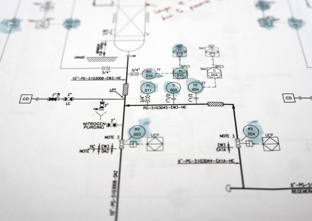
When investigating an industrial incident, one piece of information I always ask for is the relevant P&ID’s for the process. P&ID stands for Piping and Instrumentation Diagram and is defined as “A schematic diagram of the relationship between instruments, controllers, piping, and system equipment.” A set of P&ID’s for an entire facility allows you to trace the entire manufacturing process from raw material unloading to finished product loadout, including utilities like steam, water, fuel, and air. That’s great information to have but isn’t especially useful in an incident investigation. However, the information from the P&ID’s covering the vessel or vessels involved in an incident can be very useful.
In a previous blog, I wrote about the distributed control systems (DCS) that manufacturers use to monitor and store process data such as temperatures, pressures and flow rates, etc. The P&ID for those processes will show where these measurements are taken. Not physically, as in, “the flow meter is located on the northwest corner of the third floor”, but relative to the rest of the process, “the flowmeter is located downstream of the discharge pump and upstream of the split between Vessel A and Vessel B.”
The symbology and abbreviations used on P&ID’s typically come from one of two standards: “ANSI/ISA-5.1 Instrumentation Symbols and Identification” or “PIP PIC001 Piping and Instrumentation Diagram Documentation Criteria.” These are both real page-turners! Actually, they are jam-packed with useful information that is, by definition, pretty dry. They lay the groundwork for how to read the instrument identifications (tag numbers) on the drawings. Part of the symbology shows whether a measurement point is being tracked by the DCS, and therefore, useful in investigations.
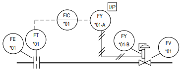
P&ID’s also let you see the control loops in a process. A control loop is a collection of equipment that will control a part of a process. Let’s say you have six identical reactors, then TIC-100 could be a temperature indicating controller on Reactor 1, TIC-200 on Reactor 2. The P&ID will show that the temperature controller for each reactor works by opening or closing the valve in the steam supply to the reactor’s heater. The math behind how the controllers determine when and how much to move the valve opening is emotionally scarring, by the way.
In another example, let’s look at a tank that has a level controller. It controlled the tank level by sending a signal to a flow controller in the discharge line. This signal adjusted the setpoint of the flow controller. To keep the level at 50% required an outflow of 100 lb/min of material which normally required the flow control valve to be 35% open. Over time, the flow stayed the same to control the level, but the valve opening went from 35% up to 100%, indicating something was impeding flow from the tank. Subsequently, the valve in the discharge line stayed at 100% but the flow started dropping off from the 100 lb/min needed to keep the level at 50%, so the level started to rise. If this was a tank overflow incident I was investigating, then the P&ID’s would show me the tags for which I would request process data from the DCS. That data would tell the story written above.
An example of a control loop and tag numbers:
In addition to providing information about control loops, P&IDs are incredibly useful when authoring a Lockout/Tagout or Confined Space Entry procedures. When I was in manufacturing, we had reactors that were twelve feet in diameter and over one hundred feet tall. To physically survey something that big to try to find all the isolation points would be, as my husband would say, a “low percentage move.” Instead, pull out a P&ID and every pipe leading to and from a vessel is right in front of you. Feed lines and product outflow are no brainers, but would you have missed the nitrogen blanket feed line at the top of the vessel in the field? Maybe.
P&ID’s are identified in the OSHA PSM standard (29CFR 1910.119) as part of the process safety information that must be compiled before any hazard analysis is performed (reviews included). Manufacturing processes covered under the PSM standard, must make sure their P&ID’s are accurate and up to date as part of the ‘Management of Change’ requirement of PSM.
So, if you ever find yourself needing to investigate an incident at a manufacturing facility make sure to ask for the P&ID’s, or your expert surely will.
If you would like more information regarding this topic, please contact Jennifer Morningstar, B.S.Ch.E, P.E., CFEI at 803.732.6600 (office) or email her at jennifer@warrenforensics.com.
This is a publication of Southern Loss Association, Inc., P.O. Box 421564, Atlanta, GA 30342. The articles published on this website are in a general format and are not intended to be legal advice applicable to any specific circumstances. Legal opinions may vary when based on subtle factual differences. All rights reserved.